Servicing the Generation-2 Time/Strike Movement
The Generation-2 movements entered service in 1928 and were used until the end of electrically wound clock production in 1931. They were available in Time-Only (A), Time-Strike (B) and Jewelers Regulator (C) versions, and can be identified by their “round” winding motor, versus the “square” motor used on Generation-1 movements. The vast majority of Type-A movements used oval 7-jewel platforms, however, there are rare instances where these oval platforms were converted to 11-jewel. The Type-B movement was available with either an oval 7-jewel or a round 11-jewel platform. The 11-jewel Type-B models have highly damasked plates and are considered the best movements ever made by Sangamo. The Type-C movement is Time-Only, but larger than the Type-A and is used only on clocks with a sub-seconds dial.
Servicing a Sangamo Electrically Wound clock movement is broken down into 4 separate jobs.
- Servicing the Movement
- Servicing the Motor
- Servicing the Platform
- Servicing the Mainspring
These instructions will focus on servicing the movement, but all 4 jobs must be completed as instructed to ensure proper operation of the clock.
The following instructions are based on the assumption that the repairer has a working knowledge of basic clock repair techniques. CAUTION: Like a French Movement, the pivots are small and need to be well polished. Bushings must fit closely and be accurately located. Failure to handle components with care can and will have catastrophic results.
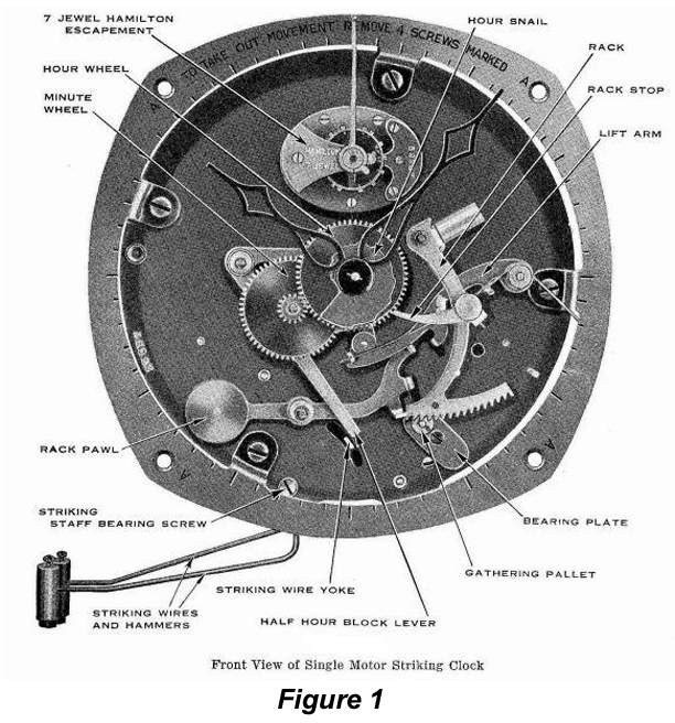
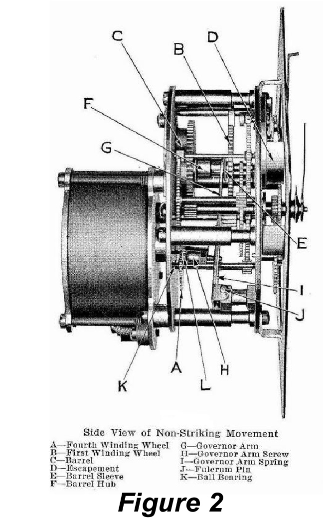
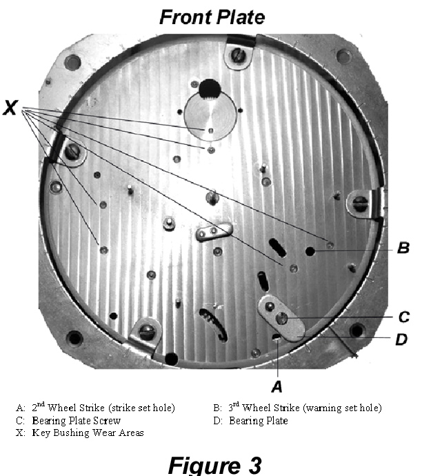
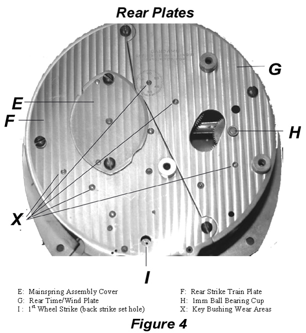
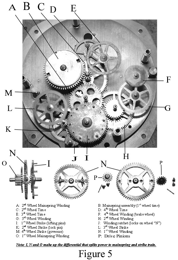
The next 5 diagrams list the names and location of the various components used in both the Time-Only and Time-Strike movements. Figure 1 shows the parts on the front of the Time-Strike movement. Figure 2 shows the internal gearing and controls of a Time-Only movement, which are of the same basic construction as the Time-Strike movement. Figure 3 identifies key wear and service inspection points located on the front movement plate while Figure 4 does the same for the rear movement plates. Figure 5 identifies and shows the location of all the wheels in a Gen-2 Time-Strike movement. It is recommended that you print these pages to use as a reference while reviewing these instructions.
Servicing the Movement
DISASSEMBLY
From the FRONT of the movement do the following:
Remove the platform (carefully) and set aside.
From the BACK of the movement:
- Remove the one long screw at the top of the motor and then the 2 short screws on the bottom of the motor. Carefully remove the motor and set it aside.
- Remove the fulcrum pin and then the governor arm assembly.
- Remove the Mainspring Assembly cover and then the mainspring assembly.
From the FRONT of the movement do the following:
- Remove the staff bearing screw and remove the strike hammers.
- Remove the hour snail, minute wheel (be sure not to lose the tension washer under the cannon pinion).
- Remove the half hour block lever.
- Remove the rack lever.
- Remove the lift arm.
- Remove the rack pawl.
- Remove the gathering pallet (friction fit).
Note: Don’t worry about the little pieces of wire holding the levers on. They will break and will need to be replaced. Also, make sure you don’t lose the (5) little washers.
From the BACK of the movement do the following:
- Remove the 3 screws holding the Strike Train Cover and then remove the cover.
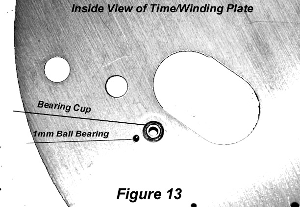
- Remove the 1 screw holding the Time and Winding Train cover and then remove the cover. NOTE: When you remove this cover watch for the little 1mm ball bearing that sits on the tip of wheel F and inside the Bearing Cup (Figure 13). I strongly suggest that you remove the cover while the movement assembly is inside a plastic tub to catch a runaway ball. If you lose the ball bearing (or if it is already missing) you must obtain a replacement for the winding train to function properly. The ball inside the tip of a ball point pin cartridge is an acceptable replacement.
CLEANING/INSPECTION
- Clean all wheels and the movement plates thoroughly; understanding that 11-jewel movement wheels are gold plated and excessive time in an ultrasonic cleaner will damage the plating.
- Inspect all pivots for wear, polish as needed.
- Install all wheels back between the plates and then inspect bushings for wear. NOTE: IN Figures 3 and 4 we have placed an “X” by bushings that “almost” always show excessive wear and need to be rebushed. The most important are the four bushings on wheels “D” and “E” and the.7mm bushing on the opposite end of the 1mm ball bearing surface of wheel “F”. At first inspection these bushings may appear to be in “acceptable” condition, however, these are very small pivots (.7 and .8mm) and a small amount of wear will effect performance dramatically. Care MUST be taken to ensure that new bushing are placed precisely.
- Wheels (O), (N) and (I) form the differential that allow the Electric Motor to wind the Mainspring, while at the same time take power from the Mainspring to drive the strike train. The most important wheel in this assembly is 1st Winding Wheel (N) and close attention must be paid to the “2” Drive Pinions (P) that are attached to it. It is recommended that you carefully disassembly and clean both Drive Pinions and axels to ensure that the rotate freely and are properly lubricated. One drop of oil at the end of each “CLEAN” axel is sufficient.
Movement Assembly and Adjustment
To assembly the movement:
- Place wheels D, E, F, G, and H into their proper location on the front Movement Plate.
- 2. Put “1” drop of oil inside the 1mm Bearing Cup in the Time/Winding Train Cover and then set the 1mm ball bearing into the bearing cup, making sure it settles into the bottom. The oil will hold the 1mm ball bearing in the cup while the Time/Winding Train Cover is installed.
- Install the Time/Winding Train Cover.
- Before proceeding check the end shake of Wheel F, making sure it is no more than 0.1 mm. If more than this there is a possibility that the 1mm ball bearing fell out during assembly. This bearing MUST be in place to ensure the mainspring braking system works properly.
- Place wheels A, C, I, K, L, M, N, O and Winding Ratchet J into there proper location on the front Movement Plate. NOTE: Wheel (O) is installed nose down, Wheel (N) is installed so the side with the “pinion mounting screws” is facing UP and Wheel (I) so that the lifting pins are facing up.
- Install the Strike Train Plate.
- Make sure all wheels move freely and that the return spring on Winding Ratchet (J) is adjusted so that the ratchet engages Wheel (N). If correctly done, the ratchet will make a steady “clicking” sound as the Winding Train is operated and it will only allow Wheel (N) to move in a “clockwise” rotation ONLY. This purpose of this ratchet is to prevent the Mainspring from unwinding during a power failure or if the clock is unplugged.
- Apply the desired amount of oil to the all pivots at this time using good synthetic clock oil.
Adjusting the Strike Train
The strike train on Type-L Movement is made in a way that has baffled many Clock Repairmen. Unlike any other clock, the strike train is designed so that when at rest, the followers for both strike hammers are positioned on top of the lifting pins and the hammers are in the full “raised” (up) position. This system is designed to allow both hammers to strike on the hour, but only one to fall on the half hour. It operates as follows:
- There is a “cam” machined onto the Cannon Pinion and while it rotates, it RAISES the Half Hour Block Lever on the HOUR and LOWERS it on the HALF HOUR.
- The Front Strike Hammer has a Striking Wire Yoke attached to its body, which extends through the front plate and comes out just below the Half Hour Block Lever.
- On the HOUR strike the cam is in its full UP position and has raised the Half Hour Block Lever so that it does NOT interfere with the Striking Wire Yoke, allowing both strike hammers to fall.
- On the HALF HOUR strike the cam has moved into its full DOWN position, allowing the Half Hour Blocking Lever to move just above the Striking Wire Yoke, preventing the front strike hammer from falling.
If the strike train is not properly adjusted and the hammers not in their full raised (UP) position when the strike train is at rest the following problems will occur:
- Clock Quits Running: If the front strike hammer is not in its full up position, the Striking Wire Yoke will “JAM” the Half Hour Block Lever when it is moving into position on the HALF HOUR. When this happens the Half Hour Block Lever will “JAM” against the cam on the cannon pinion stopping or slowing down the movement.
- Clock Strikes ONE Time 15 Minutes before the Hour: If the movement does somehow continue to run and the strike train releases, the front strike hammer will raises and with it the Striking Wire Yoke will move downward. When the Striking Wire Yoke moves down far enough, the Half Hour Block Lever will fall into place and prevent the front strike hammer from falling. You may think that this is a good thing, but you would be wrong, as this situation causes what we call “The Quarter Striking Sangamo” and it has driven many a Clock Repairmen to drink. Because the strike train is not adjusted so that the lifting pins on Wheel (I) are holding the strike levers up when the strike train is at rest, the only thing holding up the front strike hammer is the Half Hour Block Lever sitting on the Striking Yoke Wire. Now…. as the clock continues to run past the half hour, the cam on the cannon pinion begins to move the Half Hour Block Lever upwards and away from the Striking Wire Yoke. As soon as the cam pushes the Half Hour Block Lever away from the Striking Wire Yoke (about 15 minutes before the hour), the front strike hammer is allowed to fall and without the without the lifting pins on Wheel (I) to stop the fall, the hammer strikes the chime rod.
If the “warning” of the strike train is not set properly the following problem will occur:
- Clock strikes ONE TIME 5 Minutes before the Hour AND Half Hour: Since both strike hammers are fully raised when the strike train is at rest, excessive “warning” will allow Wheel (I) to move far enough that the hammers will fall from the set of lifting pins they are resting on. When this happens the clock will strike one time during the “warning” phase for the hour and half hour, stop, and then strike properly on the hour and half hour.
- Clock begins striking during the “warning phase”: In rare cases it may be necessary to adjust the tab on the Lift Arm which catches the Stop Arm on Wheel (L). If this tab is out of position (too high) during the “warning phase” it will not catch the Stop Arm when it is released during the warning phase.
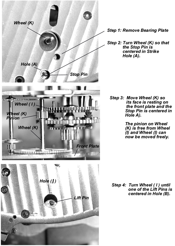
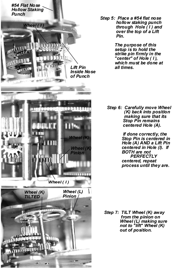
Proper Setup of the Strike Train on a Type-L Movement
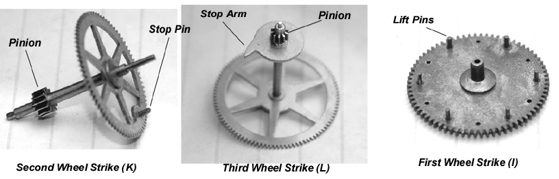
Once you understand how to do it, setting up the strike train on a Type-L movement is easy. The keys to this adjustment are the position of the 1st Wheel Strike (I) on which the Lifting Pins for the strike hammers are located and the 3rd Wheel Strike (L), which control the Warning of the strike train. The 2nd Wheel Strike (K) controls all of these adjustments, as by removing Bearing Plate (D), this wheel can be moved into a position where both Wheel (L) and Wheel (I) can be properly positioned. You must also familiarize yourself with the location of 2nd Wheel Strike Set Hole (A) and 3rd Wheel Strike Warning Set Hole (B) on the Front Plate, as well as 1st Wheel Strike Set Hole (I) on the back plate.

Once the strike train is setup properly you can reinstall all the levers and gears back onto the front of the movement and check operation as follows:
- Confirm that both Strike Hammers are in their full “UP” position when the strike train is locked (not striking). If the Strike Hammers move upwards when the movement begins to strike, the strike train is NOT setup properly.
- Confirm that the Striking Wire Yoke will clear the Half Hour Block Lever as it moves into position. NOTE: If the Striking Wire Yoke will not clear, it may be necessary to bend the tab down slightly so that it will. This should only be done if you are POSITIVE the strike train has been properly setup.
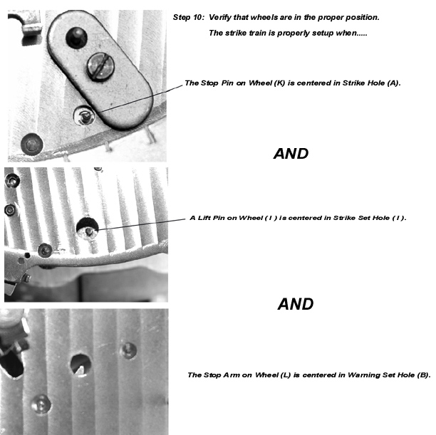
- Confirm that the Stop Arm on Wheel (L) is centered in Hole (B). This does not have to be EXACT, but the Stop Arm should be within 1/8 inch of either side of Hole (B).
You are now ready to move into the one of the following sections:
- Servicing the Motor
- Servicing the Platform
- Servicing the Mainspring