MAINSPRING ASSEMBLY SERVICE
There are basically three different types of Sangamo mainspring assemblies depending on when the movement was manufactured. The very first mainspring assemblies were simple, as there were no mainspring brake system, so no need for a barrel sleeve or guide pins. These will not be discussed as they were only used on early experimental models and a very small number of early production movements. If encountered, the following instructions will be sufficient to guide you on proper service.
The design of the Sangamo Mainspring Assembly is relatively simple.
- The Mainspring Winding Wheel is driven from the winding train, Wheel “A”.
- The Winding Wheel turns the Mainspring Arbor which:
- Winds the mainspring.
- Turns the Barrel Sleeve via a Sleeve Screw in the Mainspring Arbor or Sleeve Pin in the Winding Wheel.
- The Barrel Sleeve will screw into (counterclockwise) the Mainspring Barrel as the Mainspring is being wound.
- The end of Governor Arm sits on the face of the Barrel Sleeve and as the Barrel Sleeve is drawn into the Mainspring Barrel, the Governor Arm moves downward, pivoting on the Fulcrum Pin.
- The Governor Arm Screw (attached to the Governor Arm) moves downward until it contacts the face of the 4th Winding Wheel.
- A leather pad on the face of the Governor Arm Screw contacts the face of the 4th Winding Wheel, stopping the wheel and stalling the electric motor.
- As the clock runs and the Mainspring unwinds, the Barrel Sleeve moves outward allowing the Governor Arm to rise and the Governor Arm Screw to decrease pressure on the face of the 4th Winding Wheel.
- As the 4th Winding Wheel is released, it begins winding the mainspring and this process is repeated over and over.
This system keeps the mainspring at a constant and precise tension until there is a power failure, at which time the mainspring supplies the power reserve to keep the clock running.
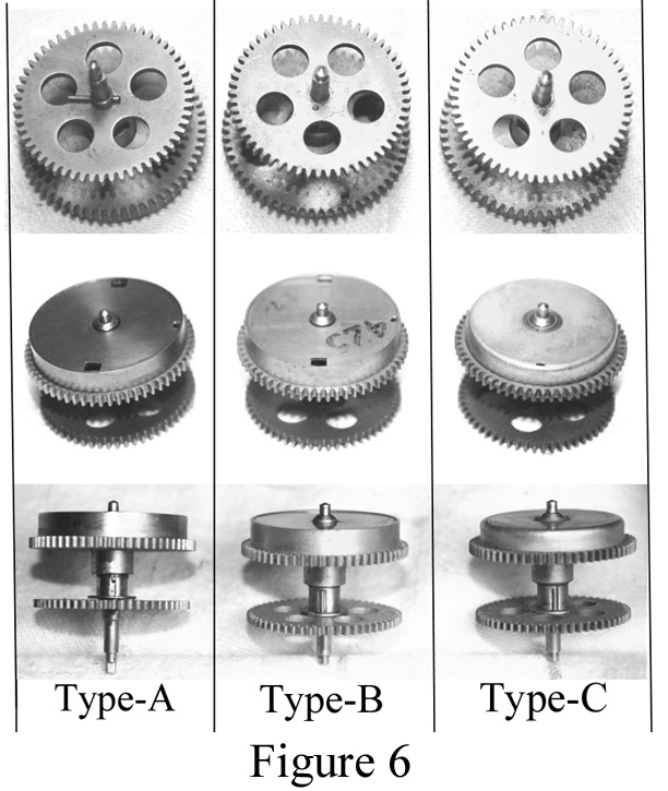
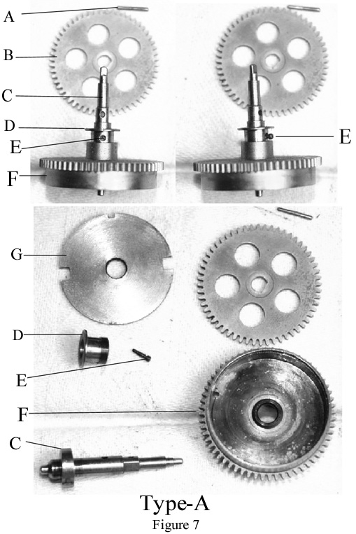
- Type-A: Has a winding wheel held on with a taper pin, a small shouldered screw which threads into the winding arbor and sits in a slot on the Barrel Sleeve, turning the sleeve as the mainspring winds or unwinds. It also has a flat snap on barrel cover. (Figure 7)
- Type-B: Has the winding wheel “staked” to the winding arbor and a pin mounted into the winding wheel. This pin sits in a slot on the top of the Barrel Sleeve and replaced the earlier “shouldered screw”, turning the sleeve as the Winding Wheel rotates and winds the Mainspring. (Figure 8)
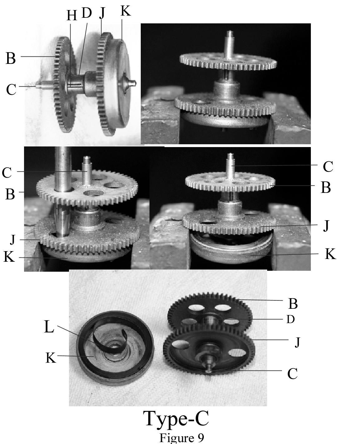
- Type-C: Is the same basic construction as Type-B, however, instead of the Mainspring sitting inside of the Mainspring Barrel, it now sits inside of a separate Spring Barrel, which is press into a groove on the face of the Mainspring Gear. (Figure 9)
The parts of the Mainspring Assemblies (Figures 8 through 12) are:
A: Winding Wheel Taper Pin I: Mainspring Attaching Clip Mounting Hole
B: Winding Wheel J: Mainspring Barrel Wheel
C: Mainspring Arbor K: Mainspring Barrel (detachable)
D: Barrel Sleeve L: Mainspring
E: Sleeve Screw M: Mainspring Attaching Clip
F: Mainspring Barrel Assembly N: Mainspring Attaching Clip Mounting Tabs
G: Mainspring Barrel Cover O: Mainspring Attaching Clip Spring Tab
H: Winding Wheel Sleeve Pin
TYPE-A
MAINSPRING ASSEMBLY SERVICE PROCEDURE
FIGURE 7
- Carefully pry off the Mainspring Barrel Cover (G) making sure not to distort or damage it.
- Carefully pull on the center coil of the Mainspring (L) and gradually unwind the mainspring out of the barrel. NOTE: There is a steel connecting piece that slips into the end of mainspring. Make sure you do not lose this piece.
- Clean the Mainspring thoroughly and apply a “light” coating of oil (I prefer Teflon) to the spring, making sure NOT to apply in excess. Too much oil is NOT advisable, as it will cause the spring coils to stick together.
- Remove Winding Wheel Taper Pin (A) and remove Winding Wheel (B) from Mainspring Arbor “C”.
- Turn Barrel Sleeve (D) until Sleeve Screw (E) is aligned with the small hole in Barrel Sleeve (D).
- Remove Sleeve Screw (E) by turning counterclockwise.
- Slide Mainspring Arbor “C” out of Mainspring Barrel (F) and remove Barrel Sleeve (D) (clockwise).
- Clean all parts thoroughly and then apply one drop of oil to the threads on Barrel Sleeve (D) and screw back into Mainspring Barrel. Apply one drop of oil to the bearing surface inside Mainspring Barrel (F) where Mainspring Arbor “C” rides.
- Reassemble in reverse order.
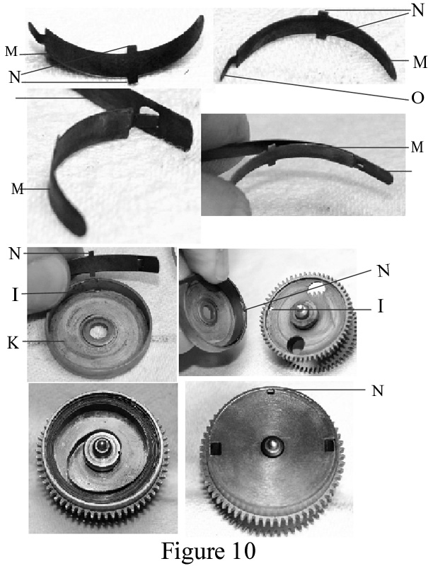
- Install Mainspring Attaching Clip (M) onto Mainspring (L) by inserting Mainspring Attaching Clip Tab (O) into the end of Mainspring (L) and position inside the Mainspring Barrel (F). In the Type-A assembly the Mainspring is installed in a “counterclockwise” rotation. NOTE 1: Mainspring Attaching Clip (O) must be installed so that Mainspring (L) is sandwiched between it and Mainspring Barrel (F). NOTE 2: Mainspring Attaching Clip Mounting Tabs (N) must be seated in Mainspring Attaching Clip Mounting Hole (I) as shown in Figure 10.
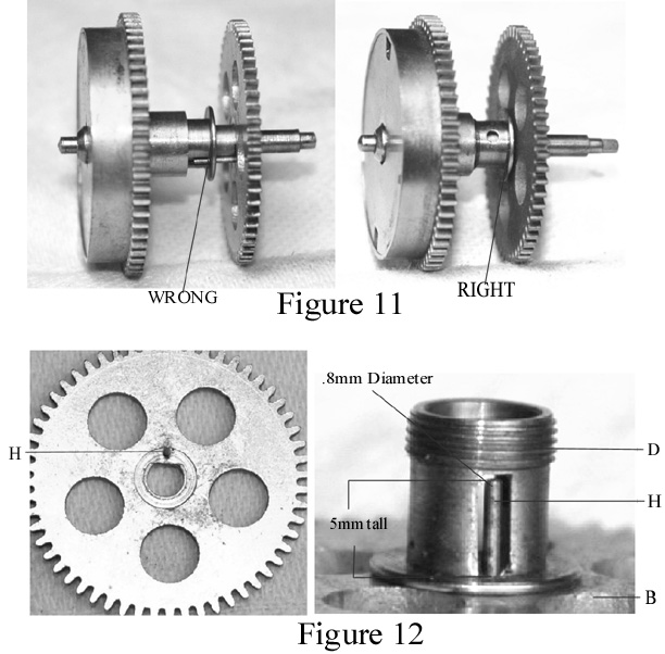
- Once the Mainspring is back in the Mainspring Barrel you must make sure that Barrel Sleeve (D) is properly positioned before reinstalling Mainspring Barrel Cover (G). To do this turn the Winding Wheel (B) clockwise with one hand, while holding the Mainspring Barrel with the other. This will move the Barrel Sleeve to its outermost position (Figure 11). Once it is in this position, turn it counterclockwise slowly until the innermost coil of the Mainspring catches the hook on Mainspring Arbor “C”, then install Mainspring Barrel Cover (G) making sure that Mounting Clip Hole and Tabs (N) align with the cover. If done correctly there should be no more than .1mm clearance between the top of Barrel Sleeve (E) and the bottom of Winding Wheel (B) and should look like the “RIGHT” photo in Figure 11.
- Install Mainspring Barrel Cover (G) and place one drop of oil to the cover where is contacts Mainspring Arbor “C”.

TYPE-B
MAINSPRING ASSEMBLY SERVICE PROCEDURE
FIGURE 8
The servicing of a Type-B Mainspring Assembly is identical to Type-A, except that Winding Wheel (B) is “staked” to Mainspring Arbor “C” instead of being held on with a taper pin. It order to disassemble this Mainspring Assembly, you must remove the Winding Wheel. To do this, support the winding wheel from the back with a suitable staking block, while using a hollow flat nose staking tool on the shoulder of the Winding Arbor to drive it out of the Winding Wheel (Figure 8). We can’t stress enough the importance of making sure you do not damage or bend the pivot surface of the Mainspring Arbor or Winding Wheel. Once cleaning or replacement of the Winding Wheel Sleeve Pin has been accomplished, drive the Winding Wheel back onto the Mainspring Arbor and then using a suitable staking tool, re-stake the wheel to the arbor. Make sure that the Barrel Sleeve and Mainspring Arbor turn smoothly and that the Barrel Sleeve will move into and out of the Mainspring Barrel without restriction.
TYPE-C
MAINSPRING ASSEMBLY SERVICE PROCEDURE
FIGURE 9
The servicing of a Type-C Mainspring Assembly is the same as Type-B, except that this assembly has a Mainspring Barrel (K) which detaches from Mainspring Barrel Wheel (J). To remove the Mainspring Barrel, place the Mainspring Barrel Assembly on top of the jaws of a small vice, letting Mainspring Barrel Wheel (J) rest “loosely” on the jaws as seen in Figure 9. Place a flat nose staking tool through a hole in Winding Wheel (B) which is aligned with another hole in Mainspring Barrel Wheel (J) and GENTLY tap or push until the Mainspring Barrel falls free. Service the Mainspring and then press the Mainspring Barrel back onto the Mainspring Barrel Wheel by pressing with your fingers or by using a suitable wood block to press it into position. Make sure that the Barrel Sleeve and Mainspring Arbor turn smoothly and that the Barrel Sleeve will move into and out of the Mainspring Barrel without restriction.
MAINSPRING ASSEMBLY PROBLEMS
The most common problems you will run into when servicing the Mainspring Assembly are a broken Mainspring, broken or missing Mainspring Attaching Clip or broken Sleeve Screw. We recommend replacing a Mainspring if it has broken, as experience has shown that it will likely break again. The specifications for an “original” Sangamo Mainspring area as follows:
- LENGTH: 36 inches long
- WIDTH: 4.5mm
- THICKNESS: Between .0061 and .0075 inches.
Sangamo originally matched Mainsprings to the movement to get the proper amplitude of the balance, however, experience has found that a .0070 Mainspring works very well in all movements and if too strong, the Governor Arm Screw can be adjusted to apply sooner and reduce the effective spring tension.
If the Mainspring Attaching Clip is broken a new one will have to be fabricated. This clip plays a very important role as it supports the end of the Mainspring when it is fully wound and without it the constant winding and unwinding of the Mainspring during operation would weaken and break the end of the Mainspring.
A broken Sleeve Screw is another problem that must be corrected or the Barrel Sleeve will NOT be rotated with the winding and unwinding of the Mainspring Arbor, rendering the Motor braking system inoperative. Unless you have a ready supply of small screws of the proper pitch that you can modify or have the tools and skill to make a new screw, your only alternative is to modify Winding Wheel (B) and Barrel Sleeve (D) to the later style of the Winding Wheel (B) with Winding Wheel Sleeve Pin (H) as seen in Figure 8 on the later Type-B Mainspring Assembly. The Barrel Sleeve (D) will also have to be modified like the picture of the Barrel Sleeve (D) in Figure 8 by filing small slots into the top of the Barrel Sleeve for the Winding Wheel Sleeve Pin to enter the Barrel Sleeve. Figure 12 shows the proper location of the pin on the Winding Wheel and the proper height and diameter of the pin from the face of the Winding Wheel. Take your time and you will do fine.